Daniel MEGE
RESEARCH


Scaling laws for dyke propagation
Length vs. maximum displacement
LENGTH VS. MAXIMUM DISPLACEMENT
and implications for the maximum depth of LEFM applicability (at least in the study area)
For most fracture types a linear relation exists between length L and maximum displacement Dmax. Field evidence usually shows that
![]()
where a = 1 and g ranges between 0.1 and 0.001. This rule works surprisingly
well for a given fracture population that is not restricted by mechanical
discontinuities; the observed data scattering is explained by the difference
in linkage stage among the studied fracture population [1]. The value
taken by g depends on rock type, water content, and planetary size (gravity).
In a population of 39 basaltic and silicic dykes intruding the basal Trap
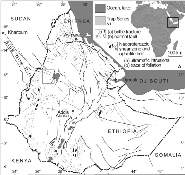
Series observed in northwestern Ethiopia (Metekel and Qwara districts,
Figure 1), Dmax and L could be
measured with some accuracy by combining field and high resolution satellite
image data (SPOT5 @ 2.5 m/pixel).

Figure 1 : Location of the study area in Ethiopia
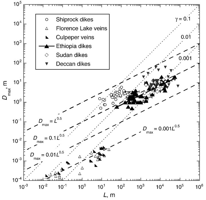
The exponent of this population is 0.48 (Figure 2). The behaviour of silicic and basaltic dykes is not significantly different; counting them in the same population improves the correlation coefficient (0.69) [2].

Figure 2: Length vs. maximum displacement for 39 studied Ethiopia dykes and other dykes and veins which dimensions were found in previous papers. These populations are better fit by a square-root law (dashed lines) than a linear law (dotted lines) [2].
In contrary to faults, which propagate under constant driving stress and
for which a linear relation between Dmax
and L can be demonstrated, a = 0.5 show that the studied dykes
were shallow enough to propagate under constant fracture toughness, i.e.
their growth was regulated by the near-tip properties of the intruded
rock. This is theorized by Linear Elastic Fracture Mechanics (LEFM), which
predicts that
where KIC is fracture toughness in mode I (opening), n is Poisson's ratio, and E the Young's modulus of the basaltic rock mass, shows this square-root dependence.
However, this equation considers that dyke is infinitely tall. It is clear though that all the silicic dykes and many basaltic dykes should have erupted [3], and it can be shown that a more realistic fracture toughness is ~1/3 the value given by this equation [2], which gives 77 < KIC < 273 MPa.m1/2. Similar KIC values have been obtained in publications on other dyke populations.
Such values are much higher than laboratory values, 2-3 MPa.m1/2. This
difference is explored by considering the following effects:
-
Laboratory measurements of KIC are for intact rock; however, intact basalt fails in tension for a few MPa only at low confining pressure, so that a damage zone propagates ahead of the dyke and dissipates much energy, which in turn increases the resistance to dyke propagation and the fracture toughness of the rock mass by a factor of at least 5-10.
-
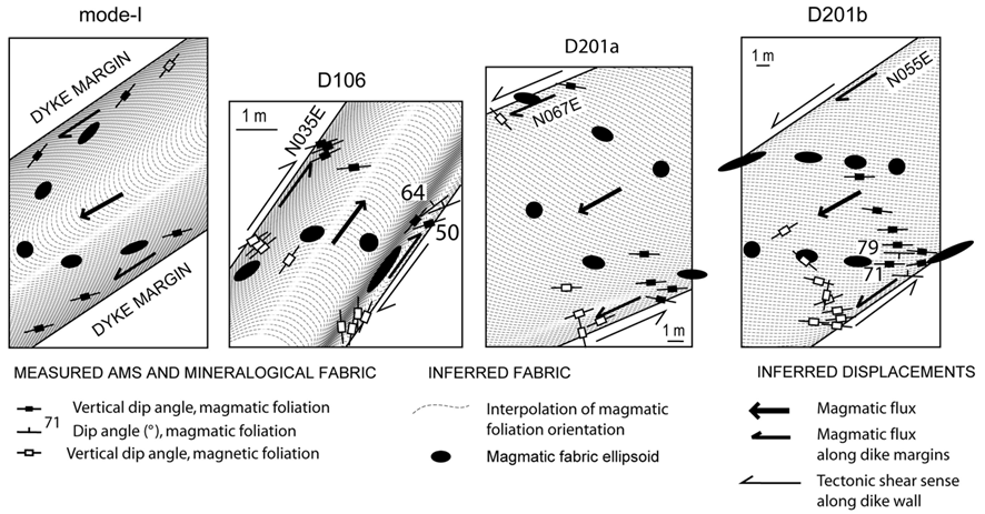
Some of the dykes in the study area display macroscopic evidence of horizontal shearing, denoting a mixed propagation mode (I-II). The magmatic and magnetic fabric of some of the 39 dykes has been analyzed and show syn-emplacement shearing (Figure 3). Mixed-mode propagation may result from dyke emplacement slightly oblique to a lithosphere fabric inherited from Panafrican tectonic events [4]. KI-IIC and KI-IIIC are invariably larger than KIC.

Figure 3: Interpreted magmatic and magnetic fabric of dykes from the studied populations showing mixed-mode emplacement. The diagram for mode I is to illustrate the theoretical patterns expected in case of dyke propagation in pure opening [2].
-
There is also field evidence that at least in some instances the dykes were emplaced in still hot, pasty lava flows. Fracture toughness increases with temperature if the temperature increases by 100-150°C.
-
The fluid-dynamics history of dyke propagation at deeper crustal level, where LEFM does not apply, has not been taken into account, it is expected that the high value found for KIC is larger than the value that would be appropriate for dyke propagation over most of their height within the crust.
Fracture toughness controls dyke propagation only if cohesive stress Sc
at dyke tip exceeds confining pressure Pc. Laboratory
samples yield Sc ~ 10 MPa, restricting the validity
of LEFM to the upper 400 meters of the Ethiopian crust. The present dyke
exposure level is at a paleodepth of 1000-1500 m, suggesting that at Pc
~ 30-40 MPa LEFM is still applicable.
... which may help identify eruptive dykes!
In construction... See the paper by Mège and Korme in the publications list (JVGR n°131) for more information.
References
[1] R.A. Schultz, R. Soliva, C. Okubo and D. Mège, 2009, Fault populations. In R.A. Schultz and T.R. Watters (Eds), Planetary Tectonics. Cambridge Univ. Press, 456-509.
[2] R.A. Schultz, D. Mège and H. Diot, 2008, Emplacement conditions of igneous dikes in Ethiopian Traps. J. Volc. Geotherm. Res., doi:10.1016/j.jvolgeores. 2008.08.012.
[3] D. Mège, and T. Korme 2004, Fissure eruption of flood basalts from statistical analysis of dyke fracture length. J. Volc. Geotherm. Res., 131, 77-92, doi:10.1016/S0377-0273(03)00317-2.
[4] D. Mège and T. Korme, 2004, Dyke swarms in the Ethiopian Large
Igneous Province: not only a matter of stress. J. Volc. Geotherm. Res.,
132/4, 283-310, doi:10.1016/S0377-0273(03)00318-4.
